
Introduction
3D printing is a disruptive technology, which is rapidly evolving. Although it is commonly seen as a “playing tool” which produces “pretty” objects, its potential is far superior. The following example shows that 3D printing technology can produce a working crank mechanism, demonstrating that, through additive manufacturing, people can realize complex functional mechanical parts. This application has been realized as a project for the course “Virtual Modeling and Additive Manufacturing”.
Idea
Such mechanism required printing and assembly of different parts, so few intermediate steps characterized design and production phases.
Initially, the best way to assemble the entire mechanism had to be found, in order to maintain the proper clutches within the established tolerances. Particular attention has been given to the rod-pin-piston group, within which the pin must be locked to the piston, in such a way that contact between pin and cylinder does not occur. Additionally, since the piston outer surface’s and the pin holder’s axes of symmetry are mutually perpendicular, it is implied that one of the two surfaces incurred in the staircase effect (Fig. 1).
![Fig. 1: Staircase effect [1]](http://www-4.unipv.it/3d/wp-content/uploads/2017/03/staircase_effect.png)
Fig. 1: Staircase effect [1]
Both these issues have been overcome by printing a pin with a structured shape (Fig. 2), designing it in such a way that further post-processing would not be needed and the required tolerances would have been respected.
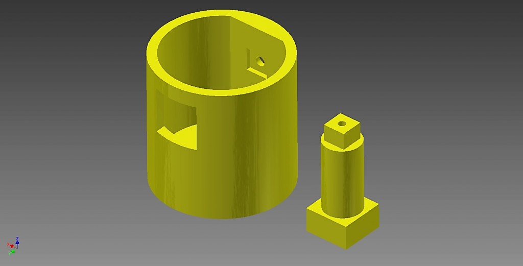
Fig. 2: This part consists of a 6 x 6 mm square-bottom parallelepiped, a 10 mm diameter cylinder and a 12 mm x 12 mm square-bottom parallelepiped. The pin is inserted on the side of the small parallelepiped through a 12 x 12 mm hole; inside it will be matched to the connecting rod along the cylindrical section and then will fit onto a flat protrusion purposely generated inside the cylinder.
Production
Most of the mechanism components have been printed with Fused Deposition Modeling (FDM) technology, while the remaining pieces (the transparent ones) with Stereolithography (SLA). In order to avoid the staircase effect, parts have been printed orienting their cylindrical section axes vertically. The printing process has been carried out in such a way that the least amount of support structures had to be used, to reduce the post-processing phase time. Once every part has been printed, they have been assembled and a working crank mechanism has been obtained.
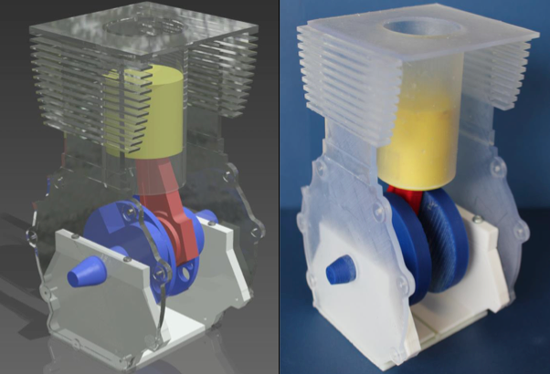
Fig. 3: Assembled crank mechanism: rendering (left) and 3D-printed (right)
Video 1. Crank mechanism assembly – Ing. Stefano Gilardoni
References
[1] Sikder, S., Ahmad Barari, and H. A. Kishawy. “Effect of adaptive slicing on surface integrity in additive manufacturing.” ASME 2014 International Design Engineering Technical Conferences and Computers and Information in Engineering Conference. American Society of Mechanical Engineers, 2014
